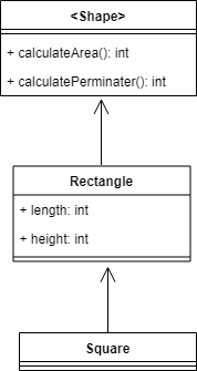
The Liskov Substitution Principle is the idea that all the children of a class can use their parent’s methods on themselves and not cause any problems. In the diagram above, the square and rectangle classes should be able to use their parent’s methods to calculate the area and the perimeter without crashing the program. The obvious benefit is that you don’t get unexpected behavior such as wrong output or having the program crash
Law of Demeter Principle: The Law of Demeter is the principle that a class should only communicate with its neighbors and not strangers.
Law of Demeter example: If we are creating a program to provide users with information for their scheduled airline flights, you would have some code that would look like this:
The code example will take you some time to figure out what it’s testing for, the code should be doing this instead:
flt1.itineraryIs( “ROC”, “JFK” )
The reason this is better is that you can see exactly what the current test is testing for instantly and you aren’t creating unnecessary relationships between the classes which is one of the benefits of using the Law of Demeter Principle. Lastly, another benefit of using the Law of Demeter Principle is that it makes your codebase easier to read since you don’t have to spend time figuring out what it’s trying to do.
Footnote: I made the Liskov Substitution UML diagram
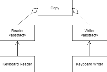
Dependency Inversion is the principle that high-level classes shouldn’t be directly communicating with low-level classes. To solve this problem, you should create a layer of abstraction between the two classes. The benefit of using the Dependency Inversion is that is easier to make changes in the future if either the low-level class or high-level class were to change.
Dependency Inversion example: In the UML diagram below, you can see that the Copy class isn’t directly communicating with the keyboard reader and writer classes.
Copy diagram
Open/Closed Principle:
The Open/Closed principle can best be summed up as “A class should be open for extension but closed for modification”(Joshi).
Open/Closed example:
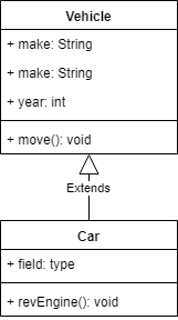
In the UML diagram below, you can see that the Vehicle class is open to being implemented while not allowing the Car class to modify any of its implementations.
Vehicle UML Diagram
The benefit of the Open/Closed principle is that it allows new functionality to be added on while minimizing the risk of breaking everything.
Footnote: I got the copy diagram from Bob Martins website Martin, Bob. “The Principles of OOD.” December 5, 2012. Accessed April 24, 2019. Joshi, Bipin. Beginning SOLID Principles and Design Patterns for ASP.NET Developers. New York, NY: Apress, 2016. I made the vehicle UML diagram
The Pure-Fabrication principal is the idea that when you are adding a new feature to the product and review each of the classes that you currently have and their specific responsibilities so as to determine whether you need to create a new class to handle this new feature. This is because all the classes that currently exist don’t have the same responsibility as the new feature you would like to add.
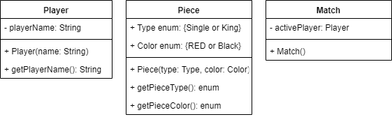
Pure-Fabrication example: Using the UML diagram from the web application checkers game example outlined above, say, for instance, I would like to add the feature to allow the ability to make a move in a game of checkers. With the current classes that are currently available, a new class would need to be created as the responsibility of making a move doesn’t align with any of the other classes responsibilities.
web application checkers game UML diagram
By creating a new class to perform a move in a game of checkers, I’m making sure that none of the existing classes become responsible for something that they shouldn’t be responsible for. When I use the Pure-Fabrication principal, I’m making sure that my classes have High Cohesion and Low Coupling.
Single Responsibility Principle: The Single Responsibility principle states that every class should have a single responsibility for which it would be held accountable for performing. Martin gave a good explanation of the problems that arise when the Single Responsibility Principle isn’t followed when he said, “If a class has more than one responsibility, then the responsibilities become coupled. Changes to one responsibility may impair or inhibit the class’ ability to meet the others.”
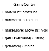
Single Responsibility example: In the UML diagram below, you see a class called GameCenter and it seems like it has responsibilities that it shouldn’t have. A GameCenter is used to help keep track of all the ongoing games so it is not necessary for the GameCenter class to have the methods makeMove and getPlayer responsibilities since both methods give the GameCenter class responsibilities that it shouldn’t have.
GameCenter Class UML Diagram
The benefit of the Single Responsibility principle is that it helps with debugging. If something goes wrong you have a better idea on where the bug is located based on what went wrong. Also, It helps make the codebase more maintainable since it keeps the codebase organized and easier to implement new features.
Footnote: I made both UML diagrams Martin, Bob. “The Principles of OOD.” December 5, 2012. Accessed April 24, 2019.
The Controller principle is the idea that the UI (User Interface) classes should be separate & apart from the non-UI classes. The separation assists the code writing team with debugging & helps make the codebase more organized. More importantly, the separation is essential as the UI should not have direct access to the rest of the program in order to prevent any possible damage from UI infiltration within the written code.
Controller example:
Grand gave a great example in his book when he said, “Suppose you are designing a security system. The security system is attached to numerous devices that sense the opening of doors and windows, motion within a building, and other events. You don’t want the external devices or the objects responsible for receiving the raw input from the devices to send any events directly to the objects within the security system that will handle the events”.
The benefits of implementing the Controller principle are numerous. First off, it allows the program to error checks the input. Secondly, it appropriately relays the input to the correct destination. The third benefit that the Controller principle provides to the written code is that it adds a layer of abstraction to the code that makes it more flexible when it comes to making changes in the future; whether it’s a change to the destination or the how the input is handled.
Polymorphism principle:
Polymorphism is a layer of abstraction that provides assistance when you have classes that contain very similar methods/attributes in several classes. It allows you to write the common methods/attributes i. A single place but have different implementations in the classes that differ.
Polymorphism example:
Let’s say you are creating a program to keep track of all the different animals that exist in the world for scientific simulations. It’s easier if you create an abstract class that contains all the similarities between several classes. In the example below, I placed the attributes that both a bee and a cat have in common in the animal abstract class. Since cats and bees both make different sounds, they will have to implement their own methods for producing sound.
abstract animal UML diagram
The benefit of using the polymorphism principle is that it helps reduce the chore of rewriting code several times when you can simply do it once. This is because the classes that extend (use), the abstract class, inherit all the attributes/methods that are in common while allowing the differences to have their own implementation. Another benefit of the Polymorphism principle is that it helps make you have a more organized codebase.
Footnote: I made the abstract animal UML diagram Grand, Mark. Patterns in Java. 2nd ed. 2 vols. Hoboken, NJ: Wiley, 1999.
To understand what Low Coupling and High Cohesion are, you need to understand what the words Coupling and Cohesion actually mean. Coupling is the focus on the complexity between itself and other classes, while Cohesion focuses on the complexity within its own class. With this understanding of the terms Coupling and Cohesion, we can now explore the principles associated with these terms.
Low Coupling: When you are creating a new class, you want your written code to have only the necessary number of relationships with other classes. This is critical, as any relationship exceeding the required amount results in written code with unnecessary relationships or “clutter” that will become problematic when the code-writer goes about debugging the code or having to maintain it. This is because the relationship between the classes within a string of written code or “ribbon of code” are all mutually dependent on the other classes within the “ribbon”.
High Cohesion: When creating a new class, you want your class to perform just a single task and nothing else or, have a very clear purpose of what it’s goals are. The reasoning for adhering to this principle is that it limits the responsibility of every class; it ensures that every class is only responsible for its own tasks and does not perform any unnecessary work.
Low Coupling/High Cohesion when used together help piece together the bigger picture.
Summary: Knowledge Check of Low Coupling/High Cohesion Low Coupling and High Cohesion are very similar in that they both deal with classes that only perform their specific tasks and are not dependent on other classes to carry out their specific role. A good quote that sums up the benefits of the two related principles is, “If a class is so highly coupled or lacking in cohesion as to make a design brittle or difficult to modify, then apply other appropriate GRASP patterns to reassign the class’s responsibilities.”(Grand).
Low Coupling/High Cohesion examples: If you are creating a baseball game program, you would not want a class made up exclusively of baseball players performing the tasks (e.g. cutting the grass, working the ticket booth or selling hot dogs, soda & popcorn) that are the responsibility of a class comprised solely of the non-player personnel & staff of the baseball organization. Simply put, while the two classes have their own unique responsibilities, they have a mutual relationship, as baseball stadiums are where the baseball games are held and players participate in those games.
Information Expert: Turning now to the Information Expert principle. You use the Information Expert principle in the designing stage while you are creating the architecture of the product. The idea is that you are looking at the list of tasks you would like your product to be able to accomplish and figure out where you need to delegate the responsibilities of the tasks to the appropriate classes.
An example of the Information Expert Principle: If your end product, or desired result, was to design a web application of a checkers game, here are three sample classes that you would have:
UML (Unified Modeling Language) diagram
If your task was to add the functionality of changing the player’s name, you would look at the different classes that you have and figure out which class is the most appropriate class to add that functionality to. In the case at hand, it would make the most sense to add this functionality to the class comprised of the baseball players.
The end benefits of the Information Expert principle is that you are following/adhering to the High Cohesion Principle without even realizing it and it’s helping you keep your codebase be more organized.
Footnote: Image source link I made the UML diagram Grand, Mark. Patterns in Java. 2nd ed. 2 vols. Hoboken, NJ: Wiley, 1999.
The purpose of this blog is to educate the reader about the different design principles/ideas that are used by the Software Engineering community to make better design choices and have cleaner codebases.
Four out of the ten principles discussed in this blog are part of the S.O.L.I.D (Single Responsibility, Open-Closed, Liskov Substitution, Interface Segregation, and Dependency Inversion) principles. The Software Engineering community started implementing the S.O.L.I.D principles in their design choices and code after Bob Martin’s 2000 paper, “Design Principles and Design Patterns”. Martin wrote the paper urging the community to start using these principles to help make better design choices and have cleaner code. Martin’s reasoning behind suggesting such was, that by using S.O.L.I.D principles in their design choices and code, the Software Engineering community would not have to pay the price at a later date with having to correct their designing mistakes.
Five out of the ten principles discussed in this blog are part of the G.R.A.S.P (General Responsibility Assignment Software Patterns) principles. The principles are Low coupling/High cohesion, Information expert, Polymorphism, and Pure fabrication. They are used in conjunction with the S.O.L.I.D principles to help the end product.
The last principle that I will be discussing was introduced to the Software Engineering community by Ian Holland towards the end of 1987. Holland introduced the community to the Law of Demeter principle.
Outlined below is a listing of the principles/ideas that I will be talking about on this blog.
• Low Coupling/High Cohesion and information Expert • Controller and polymorphism • Pure-fabrication and Single Responsibility Principle • Dependency Inversion and Open/Closed Principle • Liskov Substitution Principle and Law of Demeter Principle
Footnote: Link to Bob Martin 2000 paper. Link to source for the image.